\(^ω^\) sch file. brd file. (/^ω^)/
Yeahhh so much laugh and tears. It’s a knowledgeable journey, and here’s the presentation. Ooorahh!
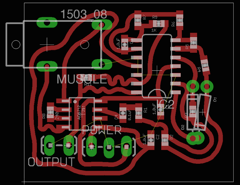
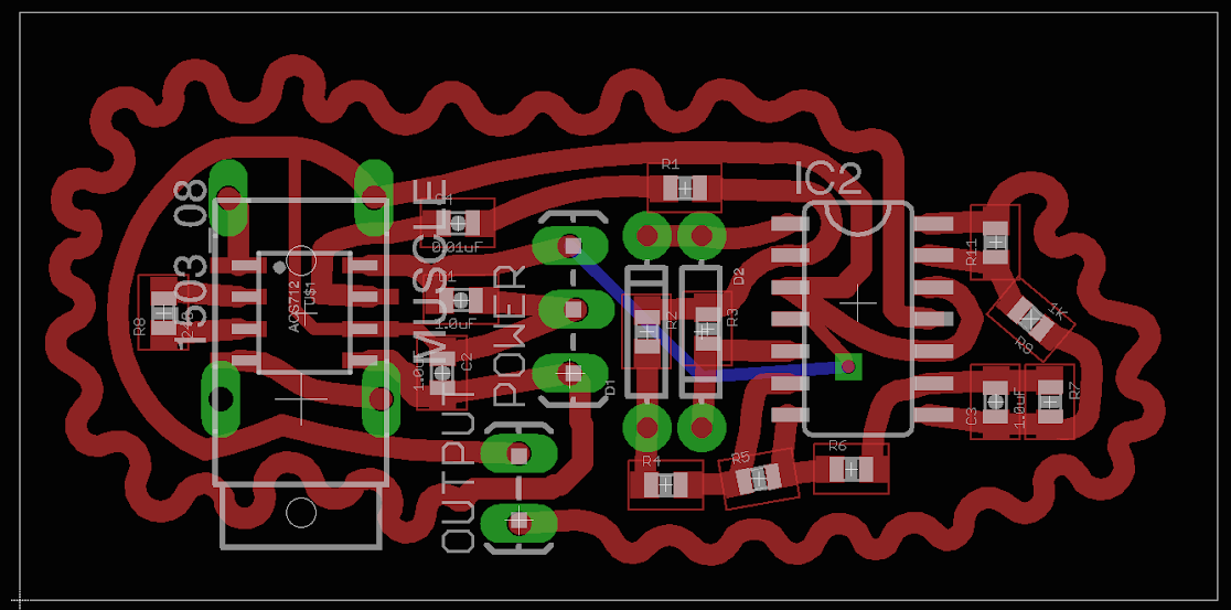
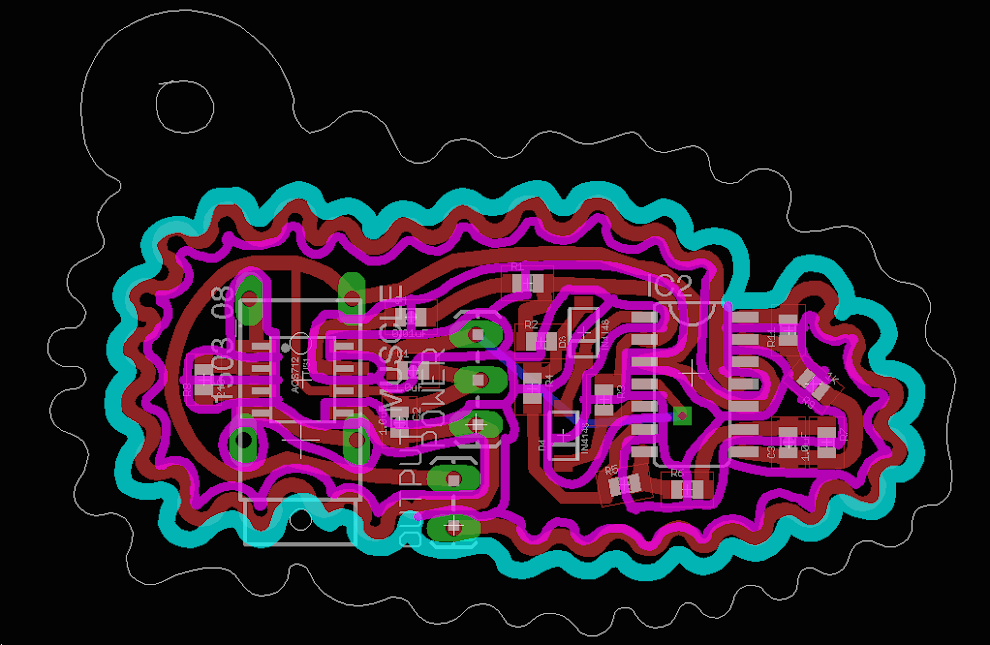
This week I finished the board design for the muscle sensor, after trying several layouts.
( old ones )
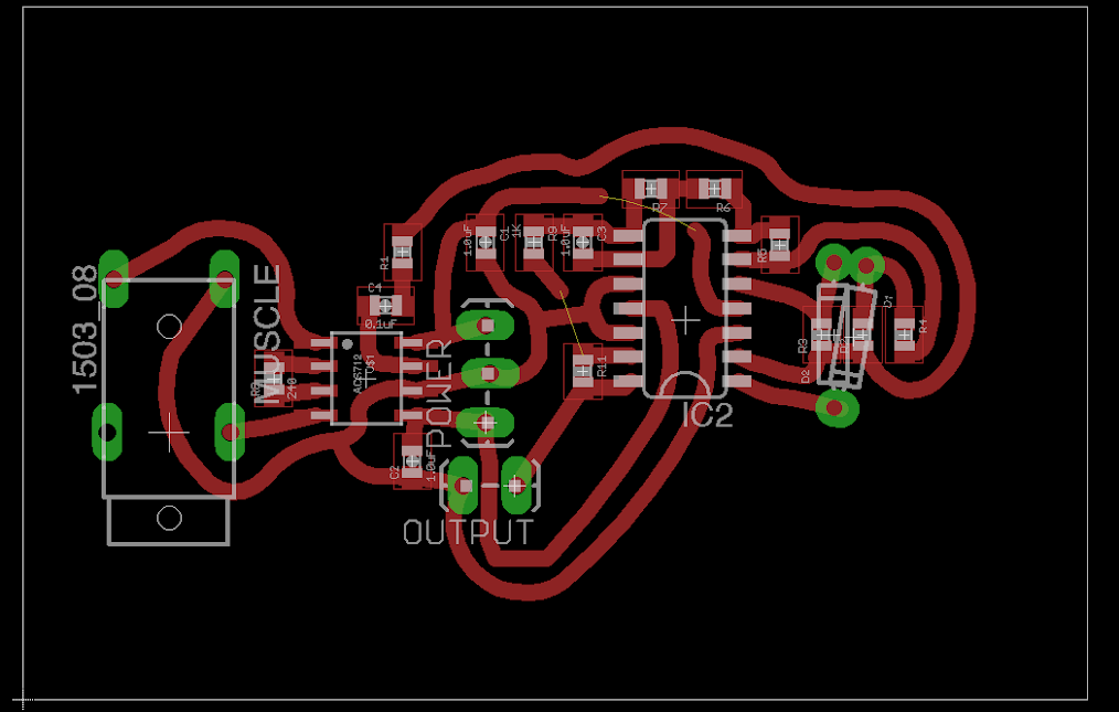
Here’s the fake final look.
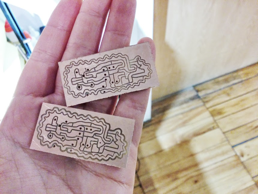
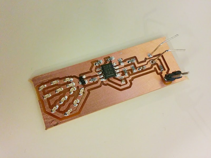
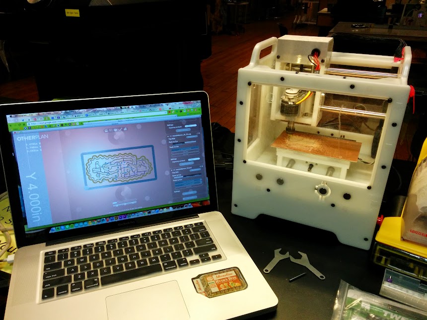
And I use OtherMill to mill the board, because the Roland can’t do the curvy routes.
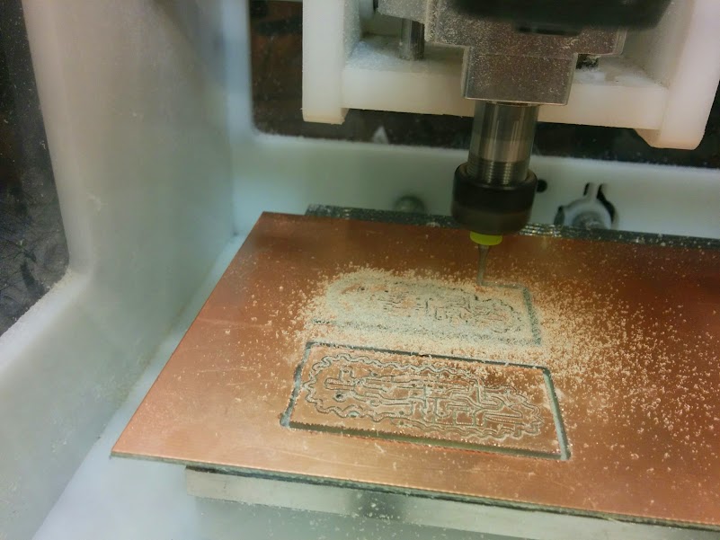
And here’s the result whoo!
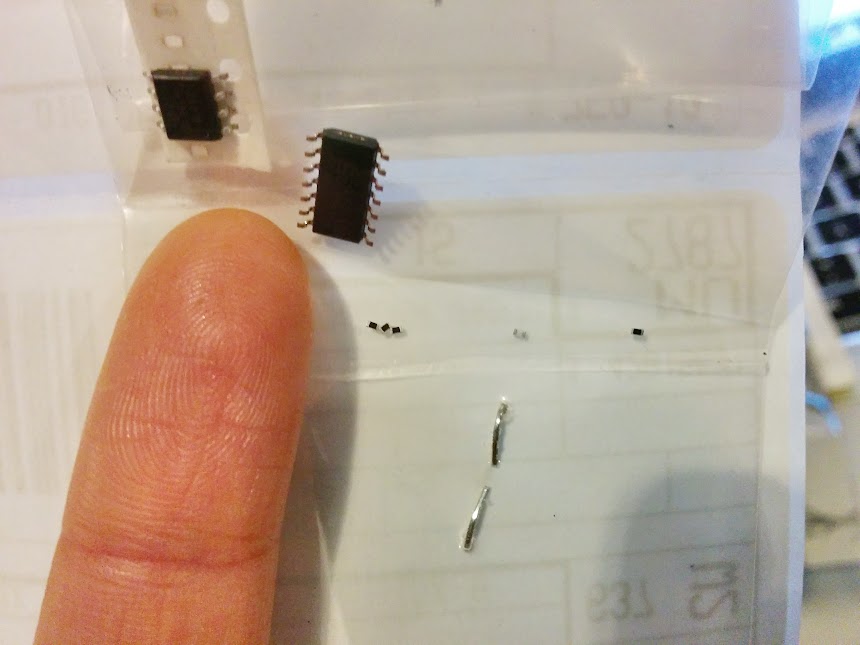
And then when I was happily ready to solder the parts on, I found out that what I ordered for the 150K, and 80.6K resistors were way too small!! Their type are 0402 instead of 0603! What was I thinking?! So tiny omg *_*
SO.
After being down for a while, I ordered parts from DigiKey again and refueled my life with hope.
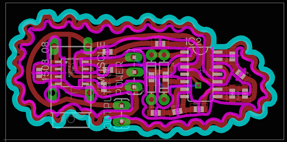
And, I also found out that I have surface mount 1N1418 diodes when I was examining my parts ( so many mistakes ooops ), so I changed the schematics again! Replacing the through hole diodes with the surface mount ones, creating curvy dimension, and a making a hole for hanging, possibly.
For my final project in Circuit Design and Prototyping, I plan to make a customized muscle sensor (EMG) for my thesis MASK, and the idea is to use the data as a measurement of mask wearer’s nervousness, and try to cope with it with MASK (virtually and hopefully also physically).
Research
Breadboarding
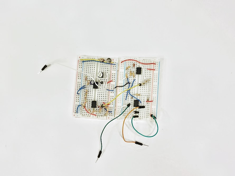
This is the first attempt to breadboard the muscle sensor, based on the design of the one on Sparkfun and also the tutorials on instructables. Because I don’t have the component, e.g. instrumentation amp, specific resistors, there are a lot of hacky moves, and I need sticker patch electrodes, 9v batteries*2, and components to know if it’s working or not :/

 <– originally thinking to hook up two power supplies, but because it requires one’s positive connecting to another’s negative, I think I should ask Eric first to see if it’s safe to do that instead of using two batteries
Next steps
Getting excited :DDD Lots of work and to be continued!

And the midterm presentation!
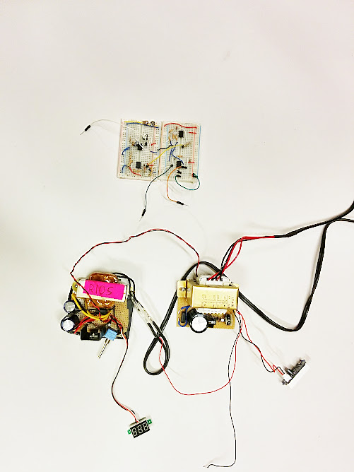
3/6
2nd try – SUCCEEDED!
3/5
1st try – FAILED!


Reference: instructables<3


Based on the tutorial of instructables, after calculation, with 9V input and yellow LEDs, I use 3 for 4 series, so total 12 LEDs, and the resistor connected to transistor will be 2.2k Ohm, and the one connected to emitter will be 22 Ohm.
The most challenging part is routing on the board. How to have an efficient route map without overlapping? Here I did a dangerous move, having a route under the electret mic, between its positive and negative hole. Don’t know if it’s doable or not.
[ UPDATED ] It’s ok to route under the mic, but should be careful not touching the pad –> adjust the width of the route to be thinner!


2/19 update, all LEDs lit up 😀
//

Took so much time!! The issue is that the solder paste got cold so fast, and put it on top of the mug warmer would make it dry fast too! T_T
The circle part is the only LED didn’t light up because I put too less solder paste. Will try it again tomorrow 😀

–> Toxic process. Detailed process please see Michelle’s post!
–> Led EYE looks very aboriginal 😀 Left one is a failure because I just ran it through the laminating machine once… Should be 3-4 times!